Crystal radios are fun for any radio amateur. They remind of the idea of wireless transmission of electricity. The energy you can get from radio waves is often quite far from that of a battery, for example. They are the first steps in understanding the more complex radio circuits.
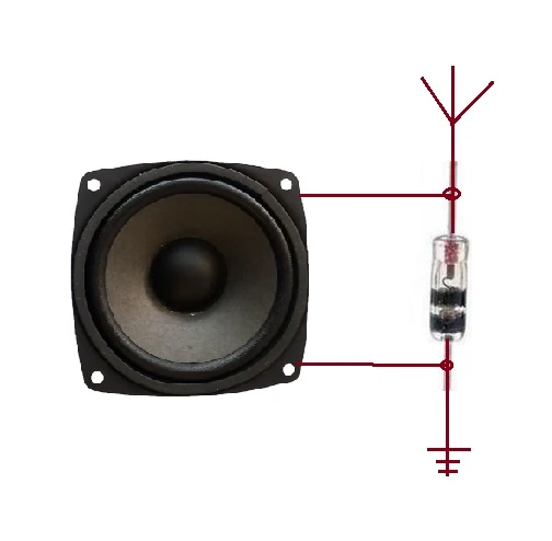
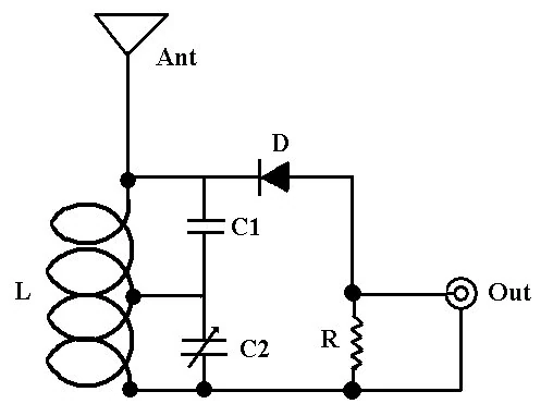
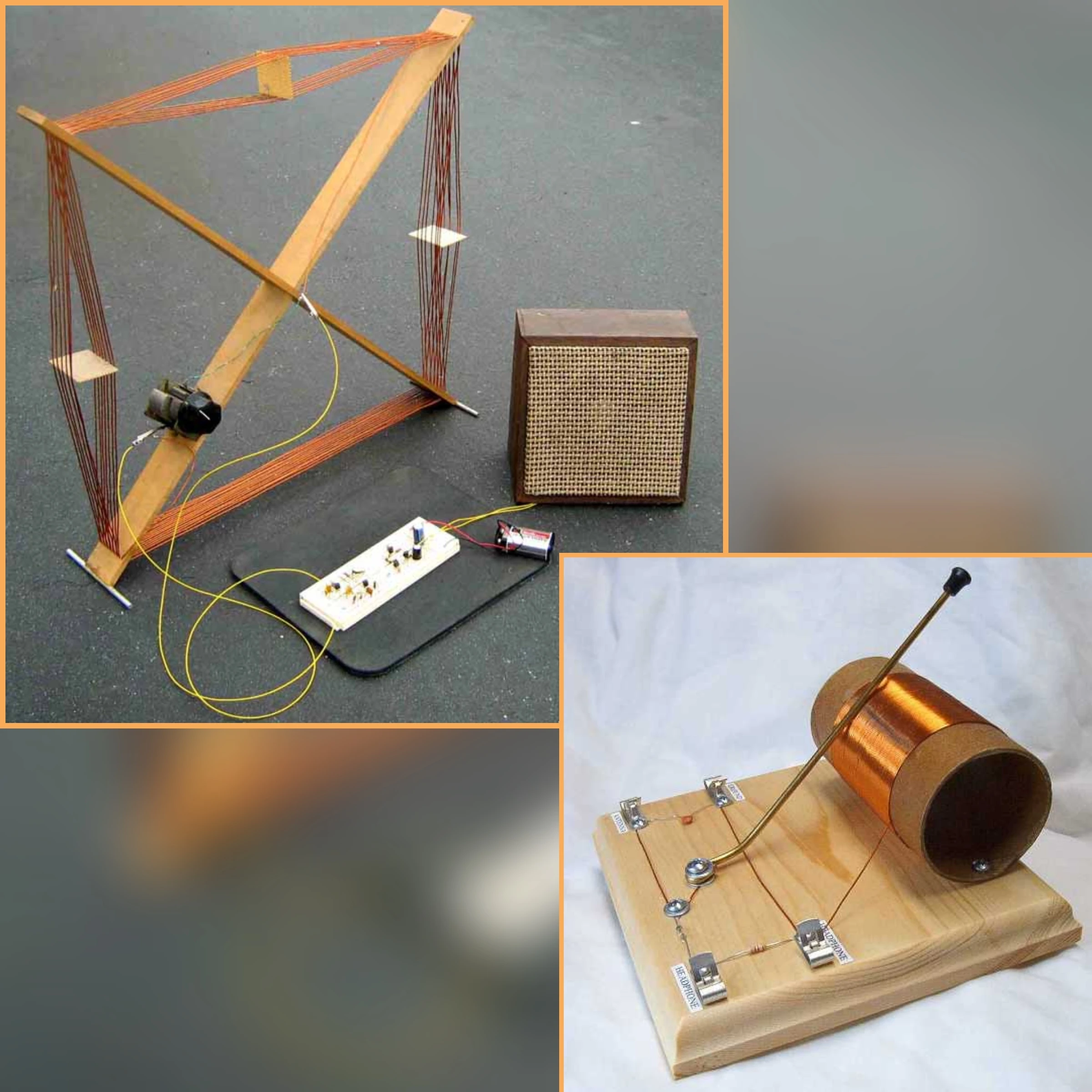
The simplest form of crystal radio.
Here are described some similarities between a crystal radio and a commercial radio.
A crystal radio is considered to be an electrical circuit based on several basic components that could be made even at home. The simplest circuit is using a diode and a sound reproducing device (speaker) connected in parallel . One or both of the connecting wires or an external metal object may be used as the antenna or grounding in this circuit. In practice, however, this is not a good configuration for long-range reception since such a circuit has low impedance to ground and cannot be tuned to obtain a useful signal value for different bands.
Therefore, in most classic crystal radios, at least one adjustable tuned circuit is used, powered by the electrical or magnetic component of the radio wave, depending on the design of the circuit.
Unfortunately, a large part of Bulgaria's medium wave and shortwave transmitters were switched off and scrapped, making the radio without external power a very difficult task. The only low power AM transmitter, which is still operating, is located in Vidin town on 600 KHz, and you still need to be there to operate the crystal radio in its classic form and it would be difficult to succeed from the first time without basic information. Medium-wave and shortwave international radio programs from neighboring countries can be captured through their reflection from the ionosphere, but only at certain times of day, under specific atmospheric conditions and clear sky mainly during the summer.
In 2019 on Bulgarian territory it is difficult for a crystal radio to operate qualitatively without its own power source and direct grounding. The power of FM transmitters today is reduced (most up to 1 kilowatt) and can hardly be detected without an amplifier in most cases, except that you have direct visibility to the antenna operating area and having a good circuit. Most of the factory silicon diodes do not work well excepting a germanium diodes and more difficult option with zener and shotkey, which can also be used by amplifier and dias circuit or you need to be very close to the transmitter.
This does not mean that the crystal radio will never work. It is a misconception that building a crystal radio is pointless today. One option is to build your own low-power AM transmitter or radiowave generator at home to try out a crystal radio. With the basic circuit during a thunderstorm, it is possible to hear radio wavepeaks of far-flung lightnings, if you have no other signals at all. In this case, the tuning is not critical.
☀However, today most of traditional free power crystal radios cannot offer much more, and the circuit already needs to use a minimum amplification and external power source.
Many of the crystal radios or transmitters offered on the Internet can be difficult to make by people without practical experience, or involve complex calculations, measurements and inaccessible electronic components. Proper practical schematics have clearly marked values and model of components, while theoretical ones are shown only as equivalent to idealized components. The principle of work is often easy to explain, but practical implementation in any personal situation is a real challenge. To understand the overall picture is necessary to research the properties of not only the receivers, but also a modern transmitters.
However, there are some simple steps that can make the simplest circuit of crystal radio work better. A successful project depends on many factors and none of them should be ignored.
Quality diodes and semiconductors []
If you really want to skip the hard search of germanium diodes and want a classical crystal radio detector, the best option is a galenna or pyrite mineral to create a ° Cat mustache ° detector with a thin conductor touching the flat surface of the crystal. This method was not accidentally used long before modern diodes. This gives you the advantage of choosing the best point of contact as long as the factory diode is fixed and can be easily damaged or broken. Often a factory made diodes can change the sounding and selectivity due to their own capacity or low operational frequency. There are also option with oxidized metals including a faimous resor blade detector, but they are less efficient and require more setup time and a stronger signal.
An effective option is to use crystal crystals from modern semiconductors. This may cost you a few tries and destroyed items until you get a suitable thickness and type of crystal at random. https: //youtu.be/uT4JouAE2WA
Some transistors might also work without any mod. A number of publications also mention certain SMD elements. Some sources also say that LEDs can be used, but mainly for the lower frequencies of short, medium and long waves. ☀It is still recommended if you going to build a crystal radio receiver for the first time to use a germanium diode.
The diode should be connected as close as possible to the end of the inductor,(coil ), if possible directly to its end, to avoid inaccuracies or losses from unforeseen inductance and capacitance. The diode is always connected to the side of the coil with a higher potential for a given frequency than the end with a lower potential and vice versa, if the diode is connected from the low potential of the coil then the other conductor must be connected to the highest potential. The second option is generally avoided as the handset or amplifier becomes part of the antenna circuit.
The main properties of the semiconductor materials used in crystal radio detector are nonlinearity and one way conductivity. Semiconductors are not the only ones exhibiting such properties, but they are much more efficient. Electrical arcs have nonlinearity properties. This is observed when an electric arc arises between the antenna of a mid-wave transmitter and the ground. From the burning of the arc, the station at which the transmitter operates is heard. Polarized dielectrics can also exhibit such properties. When the wave energy is applied, the positive values amplify the field of this source and the negative ones decrease it synchronously with the modulation.
'Common myths about crystal radio set' []
1.Myth. You cannot hear FM stations with a crystal radio.[]
/ For most radios is true, but under certain conditions it is not. /
This disinformation may have been based on the fact that mass commercially available radios would not work with an FM program when switched on to receive AM amplitude modulation. This is because of the components used in them, and overall the circuit there deliberately prevents this from happening, usually to avoid operation errors. When you switch the selector from FM to AM on commercial radio, it also changes the circuit so that you only receive medium or long wavelengths and no FM VHF, because the receiving circuit is also changed. However, this does not happen in a modern SDR software receiver, for example.
Much of the classical theory and some other articles reject the possibility of FM reception with a crystal radio detector or do not mention it at all, since virtually all crystal radios have been built for short and medium waves where an amplitude modulation is most used.
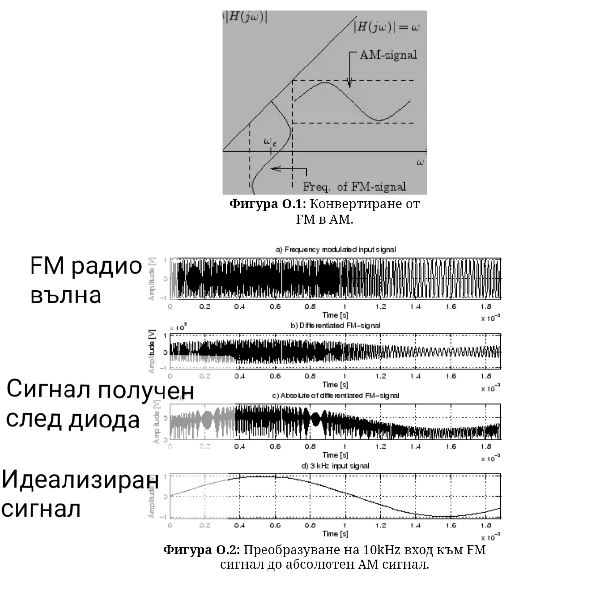
In reality, a VHFcrystal radio does not directly convert frequency changes to sound, but to amplitude changes resulting from frequency changes, which are then converted from the diode by the standard circuit. The diode itself is not responsible for FM to AM convertion. It's the resonant circuits .
In order to build a VHF crystal radio detector, it is easiest to understand the structural and technical differences in the operation of AM and FM transmitters and their commonly used antennas in practice.
'Frequency differences' .[]
Receiving FM with VHF is really difficult for the crystal radio receiver, but not impossible.
Standard mid- and long-wave crystal radio sets are often made with a large number of windings and are designed for shortwave frequencies up to 7MHz maximum, which does not allow VHF operation at higher frequencies due to high inductance and self capacitance. The inductors used for a VHF crystal radio are often just a single loop or coil of up to 5 turns, as opposed to medium and short wave coils, which can be over 10 turns and even more. The use of a small number of turns from a medium wave coil would also not work, since the remaining large number of coils are still inductively and electrically coupled and lead to a lower frequency. A very common mistake is that a very large number of turns will give more voltage to the diode. This actually takes us away from the frequencies on which the VHF crystal radio should operate. (described in the inductor section)
You have probably seen how small the coils for FM VHF crystal radios are (and even a single turn), and you might have thought it was a joke, but it really wasn't.
The amplitude modulated signal usually has only 30% demodulation coefficient, 9% useful signal and 91% DC pulse voltage. In the frequency modulated signal, the fraction of DC voltage is even higher with using diode. In modern commercial transmission techniques, the sidebands of the central carrier also contains modulation, which can reduce some of the useful signal to the VHF crystal radio.[1]
A common problem is signal intensity. Receiving frequency modulated signals is extremely difficult because the intensity in the sideband is less than in the central FM carrier compared to the usual reception in the central frequency at AM.. This value is often below the sensitivity of most headsets and diodes, and therefore requires a more precise tuned resonant circuit. ☀A low modulation index of some transmitters gives a poor signal-to-noise ratio, so a high modulation index gives a good signal-to-noise ratio.
For a medium-wave designed coil with a voltage between antenna and ground, the diode is often still subject to a small voltage difference, even without any useful signals, and this sounds like a noise. In FM crystal radio, this phenomenon is missing or noticeable only near the transmitter. This greatly reduces the options for choosing a diode and often the only option is a small amplifier or a germanium diode.
The frequencies in VHF band are absorbed much more than the atmosphere and surrounding objects and easily lose the energy needed. For the urban environment, the VHF electromagnetic fields limit is specified between 15 and 3 V / m (Volt per meter) [2].
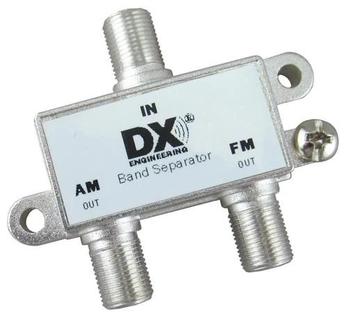
AM FM separator
Typically, in a area with a strong medium-wave transmitter, the VHF signal may remain jammed by the strong mid-wave transmitter or nothing from VHF be heard with your crystal detector. The crystal radio may not be able to completely separate both types of modulation when they have identical maximum gain, as long as this would not be a problem in a commercially available radios. There are devices and modules that can achieve this, but they are based on a modern product.
Another reason is the stray capacitance and the low switching speed of some diodes, which does not allow operation at very high frequencies. A VHF crystal radio may require even higher impedance headsets than those of a mid-wave radio. For long-distance reception they are a must.
slope detector[]

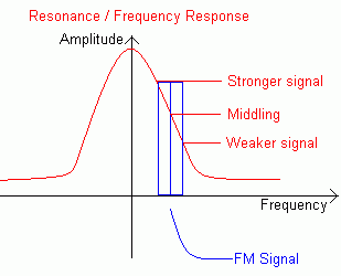
The second graph shows the energy change in the resonant circuit.
Basicly any such resonant circuit is a tuned circuit for a very high frequency in the ultra-shortwave range. However, the sound received from the circuit is the result of amplitude variation in itself.
When the resonant circuit is tuned near the central frequency of FM transmitter, the frequency variations cause the circuit to produce variable voltages depending on whether the frequency is moving away or approaching the tuned circuit resonance. This creates a kind of amplitude change as result. The output of the diode produces a mixed signal of an amplitude component, which is the sound and part of the high frequency. To filter the RF with a small choke and low pass RC filter after the diode. This output does not have the sameshape and quality signal as in normal amplitude demodulation, but it is sufficient to be heard as sound.
// The reception in the sideband can be proven and demonstrated even in modern SDR receivers through their spectral analyzer and the use of AM, FM filters. //

FM Crystal Radio
Coil for a simplified FM VHF detector receiver
If you live close to the VHF FM transmitter or have direct visibility to it, you may succeed by achieving the right inductance and orientation of the circuit and antenna. The sound may be in distortion since it will not be able to fully convert the signal to (idealized AM signal). There are usually harmonics and variations that are often of benefit to the radio detector. Filtering other radio frequencies in the city can be a particular difficulty. A good place to try is the TV Tower in Burgas.
// 'Other options.' []

Diode Frequency DiscriminatorFM Crystal Radio
Phase discriminator. Circuit of Foster Sealy. Slope detector.
Other relatively simple analog circuits have been developed that satisfactorily convert FM frequency modulation into amplitude AM. These are the so-called frequency discriminators, which include 3 different variants of circuits.
These circuits in the simplest version are using a high-frequency transformer with diodes on the secondary side and connected in parallel passive components. Much like a full bridge rectifier and transformer circuit. In older comercial radios, they are a small part of the whole relatively complex amplified circuit.
“Foster Saeley discriminator. In this detector, changing the frequency in the primary winding also changes the amplitude of the signal in the secondary winding in an almost linear relationship. In this case, reducing the frequency leads to an increase in amplitude and vice versa.
- Ratio detector or devider detector uses opposite diodes. The operation of the ratio detector is very similar to that of the discriminator, but the output is only 50% of the input signal than the output of the discriminator for the same input level.
- Quadrature detector. It does not require a central point of the transformer. It shifts the signal on 90 degrees to the carrier.
Unlike reception in the sidebar of the carrier, these three variants somewhat violate the rule of converting the radio wave by the shortest path and this is the reason that they are less popular for a crystal radio. They require such a signal level, on which the simplest option would already work satisfactorily. Ie probably unnecessarily complicated to use discriminator.
Another way to achieve a relatively good conversion is to have two tuned circuits with close resonant frequencies. The sound obtained with this method is also a result of the phase difference in the circuits. Often both methods are combined.
There are numerous designs and circuits of a VHF crystal radio operating on these principles, but overall, they are almost identical. The sound level received would ideally not exceed that of a standard MW crystal radio, unless some external gain is used.

Double tuned coil.
'It is important to note that with all of these circuits you cannot hear all FM broadcasts, since the proper operation is directly dependent on the distance to and power of the transmitter. There is a limit below which no signal can be detected with these circuits without special amplification. '
Synchronous detector. It uses more components than a regular diode detector, but with a view to mastering integrated circuit technology, it is very easy to plug into commercial radios for a minimal cost. The synchronous demodulator uses a mixer and a local oscillator. The local oscillator signal is synchronized with the input carrier.
In a modern commercial radio receivers, these methods are rarely used. Instead a digital signal processing and microchips are used. Integrated circuits are much more sensitive to frequency changes. Cheap for electronics manufacturers, and the quality of the received signal is increased. SDR receivers offer incredible capabilities.
2 Myth. The crystal radio will not work without perfect resonance.[]
As above, here also depends on the specific situation.
Resonance is a very relative concept in the real crystal radio circuit. It does not guarantee that you will hear all the stations perfectly, especially if they have far frequencies or narrowed bandwidth.
If you are a few meters away from the transmitter antannas or using some gain, even a poor tuned circuit will work though (ineffective). In such( close to the transmitter cases), a wire or an open frame such as an antenna and a good diode is sufficient to detect strongest signals. In general, the result depends on the intensity of the electromagnetic fields, which in turn depends on the distance, power of the transmitter and the polarization of its antennas.
In fact, slope detector never exactly matches the career frequency of the FM transmitter, and this is part of its principle of operation. [3] 'crystal radio will convert each radio signal, which is sufficiently intense sometimes even with quite big inaccuracy. This is confirmed by the fact that they often have poor selectivity and can hear several radio stations simultaneously and even interference. 'The reason is the difficulty in achieving a high quality Q factor. There are many different reasons that can affect the Q factor of different circuits and operating frequencies. Everything that connects in the circuit after the diode also affects this factor. Some crystal radios therefore use an inductive coupling connection as improvemet, but can be done for many other reasons.
Achieving a precise resonant circuit is important mainly for long-range reception when aiming at a maximum value of the useful signal/ noise ratio to power the headphones, for example, and to overcome the forward voltage in the diode. This will also filter out some of the weaker frequencies and interferences.
'Many different combinations of L and C values can give you the correct resonant frequency and in theory it would make no difference, but in practice, this changes the Q factor and the impedance.' Their ratio also determines the current to voltage in the circuit. An important condition is how wide range frequencies can be detected. (bandwidth density). Even a perfectly tuned resonant circuit, if it works on its own, will still receive or generate some interference, so this is why a much more complex combinations of filters, containing more than one resonant circuit are often used in more complex receivers. ☀LC values can be quite different for the same frequency, depending on whether the oscillating circuit is connected to a diode or the input of a high frequency transistor.
An idealized resonant circuit is formed by current and voltage phaseshifted to 90 * with their maximum values. When we change the capacitance, the output voltage also changes, but in order to maintain the total energy, the current remains unchanged. Conversely, when the inductance is changed, the current changes, but the total voltage remains relatively the same. The resonant circuit for a given frequency forms a relatively high impedance, which means that the rf voltage created between the antenna and the ground is not lost, but is available to be "detected" (in this case by a diode or even transistor).
// 'The farther away the transmitter is and the narrower bandwidth is, more precise the tuning would be required to receive a useful signal. //' '
The best way to make low loss resonant circuits at high frequencies is to use a helical and coaxial resonators. Inside their inductances resonate with the wall capacity of their metal boxes and elements. [4] Extra fine tuning is used variable capacitors. Coaxial resonators are most effective at 1/4 wavelength. For lower frequencies, they may be too large, but for simple detectors this can be skiped by scaling or using shortened helical windings (Helical resonators)
Quality resonant circuits in commercial radios are needed for maximum selectivity and range, and this is usually achieved through various filters, operational amplifiers and local oscillators.
3 Myths. Crystal radio does not work with steel coil / elements.[]
This is a personal choice and depends on access to the relevant materials and desired construction.
From a theoretical point of view, the use of another metal such as steel will increase the active resistance of the circuit and will reduce the Q factor and the output voltage as well. A change in inductance is possible, but often it is small. In the worst case, the output signal will be 1/2 or 1/3 less than using a copper wire. Surface corrosion will increase the resistance even more. However, this does not make the steel completely unusable at high frequencies. To reduce the resistance are often applied:
- Surface polishing and varnishing
- Coating with lower resistance metal.
- Used in combination with cheaper copper and bronze metal alloys.
A good example is some coaxial cables using a copper-coated steel core. Many of the antennas of some large mid-wave transmitters are made from steel. Aluminum and stainless steel are also used in many facilities and many commercial radio antennas. Using steel as RF conductor does not make the crystal radio useless, but it will be less effective to the weakest signals.
How your radio works with diasing silicone diodes[]
// 'An incorrectly selected diode is the most common cause of failure. The diode contains the most serious energy losses for a crystal radio detector.

The polarity of battery shoud match that of the diode. Applying the correct diasing voltage value is critical.
The basic idea for using a zener or shotkey diode is to ensure the conductivity of the diode in the nonlinear region by applying a low value DC voltage. The idea is not something new, but there is very little information about its use and it may depend on whether you will succeed or not. (If you are really close to the transmitter, this step may be unnecessary.)
Different diodes have different forward voltages and in some cases they will work well without applying dias voltage, but may not work in VHF detectors without an external source. The circuit conversion consists essentially include connections: a battery source with resistor or potentiometer, a diode (zener, shotkey) and inductance for a corresponding range of operating frequencies. The battery keeps the diode loose but still conductive so any voltage received from the antenna is added to the total voltage.. The battery can be replaced by a small photocell, but it will make noise in the circuit and increase the signal resistance.
As an important upgrade, it is necessary to ensure a smooth voltage regulation from zero to the diode operating point when high-earphones are used. It can be achieved by a potentiometer or series resistor. It is possible to build yourself a battery of copper and iron electrodes in some electrolyte, which will provide very low voltage and eventually eliminate the need for regulation. ☀However, diasing option does not always produce the best results.
Antenna []
There are two types of antennas, one receiving the electric field potential and the other the magnetic field. The electric potential usually is received with dipole antennas or just a straight vertical wire, while the magnetic fields are received with a closed wire loop with one or more turns and a cross-sectional internal diameter between 1/4 and 1/8 of the wavelength, and it also converts part of the electric potential as long as it is commensurate with the wavelength.
Most classic crystal radios use easy-to-make monopole antennas from a simple long wire. This type of antenna adds capacitance to the resonant circuit and often needs to be recalculated or adjusted.

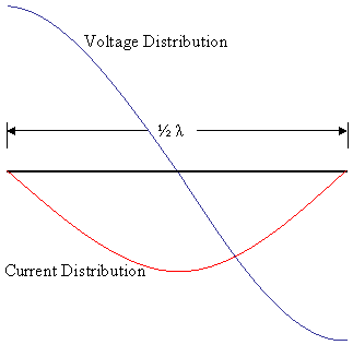
Distribution of current and woltage potencial in a wire with size of 1/2 wavelength.
Self inductance (+ active resistance) and parallel capacitance occur in all connecting wires. By incorporating various additional inductance and capacitance, the operating frequency can vary within different ranges. This can be done by changing the length of the antenna as well as its position (vertical and horizontal) and distance above Earth.
The movement of the conductors also affects the capacitance. With flexible and variable wire lengths, you may deviate from the expected result depending of frequency. Therefore, it is advisable 'that all connections between the elements be as short as possible and with good contact - solder.'
It is a common comment that the length of the antenna should be proportional to the wavelength. Some other distances in the schematics too. However, this is mainly true for high-power radio transmitters where the antenna is loaded to high power and losses would be significant if incorrectly designed.
Resonant antenna is much more important in transmitters than in receivers for a variety of reasons, but if the antenna is designed to receive only one frequency, it is desirable to reduce its response to other frequencies to reduce natural noise and artificial interference. Even so, mass manufacturers still do not produce a separate antenna for every tenth of a megahertz difference in frequency. They make it for a certain wide frequency range or apply some tuning capability. For some lower frequencies, an antenna under this condition would also be unreasonably large for the purposes of a consumer radio.
Physically, small antennas tend to have low resistance components to the radiation impedance, along with large reactive ones. This requires an impractically high Q of the tuning circuits required to drive them. The net result is more power lost in the tuning circuit.
A full-wave dipole antenna can be a bad choice. This is because of resonant currents in the antenna, which are 180 degrees out of phase each other. In the far field, these two currents get canceled.
When the antenna is used for a crystal radio receiver, the small differences are not so significant. It is recommended not to use an antenna conductor shorter than 2 - 3 meters, and for longer choices is unlimited, but it makes more sense for medium wave receiving, while at higher frequencies it may even make the reception bad.
Although in most cases each long wire can provide some electric potential from the radio wave to the crystal radio, the effective antennas are constructed with a certain geometry so that they have a good directivity and have predictable characteristics. This is often relevant for a VHF crystal radio. Targeting an antenna is the same as pointing a camcorder. The signal is strongest when the camera ( antenna ) can see and focuss the transmitter bеtter. Sometimes antennas connected in parallel can provide more gain. ☀In some cases, an oversized antenna may impair reception or tuning quality.
Improperly selected antenna length for a crystal receiver does not make it non-functional, but it may be less effective at some weaker signals or specific frequencies. It is recommended at higher frequencies where the wavelengths are relatively small, the rules of half and quarter length to be observed as much as possible.
☀In fact, radio signals will produce little electrical current in any metalic and conductive object they encounter, and not only in antennas specifically designed for a particular frequency band.
Windings and coils[]
If the coil has too many turns and has to operate at a frequency above its own resonant frequency, it will have capacitive resistance because it will have high inductive resistance in parallel with its own low capacitive resistance. In a parallel L/C circuit, the lowest type resistance dominates the behavior of the circuit.
This means that the inductor will no longer act as a coil, but rather as a capacitor, so you will never be able to make it resonate it with the operating frequency of the transmitter you are looking for, even if adding more parallel capacitance. In this case, you will only receive one or more likely several at a time or no stations.
It is recomended to use inductor with selfresonant frequency higher than receiving frequency, so the element should behave as a coil in a parallel L/C circuit where the capacitance or inductance need to be adjusted. When the inductance is low and the number of turns for a given frequency, then a little more capacitance will be needed to get closer to the resonant frequency. This will also give you a good selectivity from the upper end of the band for the selected frequencies.
However, physically we cannot use unlimited increasing capacitance to get even lower frequencies. Excess this not only reduces the frequency but also the output voltage and impedance, which is an unwanted result. The Impedance will be too low at the required frequency at some point.☀Each coil has its own resonant frequency.
In each case, a standard coil shoud not contain more than one layer of copper conductor covered with insulation. A double-layer coil would also work, but at another lower frequency due to its own higher self capacitance.
You can compensate for the small inductance with more capacitance to get the lower frequency of the station. However, if you have already received one station even without a capacitor or have passed it, you cannot tune it again with either more capacity or more inductance. The only option is to reduce the number of turns or the diameter of the former.
Ferrite core[]
Ferrite core is usen mainly for medium and long waves. It is advisable to slightly increase the number of turns instead of always using ferrite, as ferrite changes the inductance at very large range and is also less used for VHF frequencies due to magnetic losses and small changes in reactance.☀For an ideal inductor, the inductance does not vary with frequency. What really varies is reactance. In windings with an air core, the inductance is not affected by the current they carry.
'In commercial radio devices, ferrite antennas are not used at frequencies higher than 7 Mhz.' The only exceptions are transformer connections and chockes.
An exception is also when a coil is used as a choke, it is usually chosen to have a large number of turns or lengths of conductor that has high inductance for the operating frequency so that the choke has maximum impedance at a given frequency.
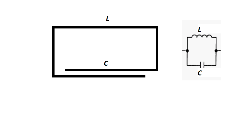

LC ratio and distribution.
Almost always, in circuit diagrams, inductance is a symbol of a three-turn winding. However, this does not mean that real inductance always uses three or very large number of turns. At high frequencies, such as in the VHF band, this can be just a straight wire loop folded in a circle or rectangle, as well as winding with up to 6 turns in the case of fixed inductance. It is more complicated if the distance between the turns is changing.

The above image receiver can operate without grounding and antenna, while the lower model is almost always required.
Dimensions and scale of coils[]
Certainly the changes in these parameters can affect the values of the inductance and the self resonant frequency. However, if we have two coils with the same inductances, but one of them is made of a much thicker wire, therefore it will be much larger in size for the same eqivalent inductance, then they would work completely identical. In commercial devices, most RF windings uses smallest diameter of wire at which the shape is maintained by itself. The exception is in power supply circuits, Including in powerful transmitters where voltages and currents are high. However, in a crystal radio, the scale of the winding is important in certain situations.
When the cross-sectional area is relatively close to the wavelength size,and the coil is resonant, then the coil can also act as an antenna on its own. In this case, it is also a magnetic loop antenna or frame antenna tuned to a given frequency. Such crystal radios usually operate without grounding and an additional antenna in most cases.
From the laws of magnetic induction we know that the area in the closed loop of a wire matters. A small coil for radio signals is actually a compact version of a larger closed loop of wire. However, the closed loop is much more sensitive to changes in surounding electromagnetic field. The small cross-sectional area of the ferrite antenna for example, will not be compensated by the increased ferrite permeability, so the loop is still better tnan ferrite antenna.
Inductors with a larger cross-sectional area may have a better quality factor. The larger conductive surface can carry more currents which helps reducing the skin effect. Copper pipes and parallel conductors are sometimes used instead of a solid cross-section to increase the conductive surface. In order for the coil to be comfortable to work with and to retain its shape and parameters, the conductor is permissible to have a much larger gauge than usual. Switching or soldering of elements is often performed directly over the conductor and it must be mechanically stable with minimal additional elements. Good apearance won't be overlooked.
Variable Capacitor[]
Any variable capacitor from a commercial radio receiver will work fine, provided some conditions are met.
It must be possible to change from minimum to maximum capacity. Its values should fall within the required capacity. At high frequencies it is possible for the capacitor parts to exhibit inductance or their own capacitance, if they are large in size, or use too long wires. Aluminum air capacitors give better results in medium waves.
The capacitor must have an insulated tip to prevent it from touching the other side elements of the circuit.
At high frequencies and VHF, the highest efficiency is achieved when part of the capacitor is also part of the inductor and there is no mechanical connection. They are all physical and their properties are smootly distributed.
☀The effect of the changing capacitance is analogous to the changes in inductance. In some situations, it is not adequate to change the inductance and the variable capacitor is the only option. Capacitor allows reaching narrower bandwidth and reactive responce in the resonant circuit than just a changes in the inductance alone.
The capacitor does not always have to be an typical connected component to the inductor. Windings have their own capacitance. In some cases, even a metal object close to the coil can affect the capacitance and accordingly change the resonant frequency without being physically connected. For fairly simple crystal radios, the variable capacitor is not an optional component, and there tuning is done by switching taps, which can be smoothed or stepped.
In many modern radios and TVs, the role of a variable capacitor is played by varactor diodes connected in pairs and controlled by reverse voltage automatically.
Headsets and phones[]
The general rule of thumb for the handset is to have high impedance. However, this is not always a sufficient condition. The much more critical value is not only the impedance, but also the electrical power of the handset. A 1W handset may be worse than 0.2W at the same impedance).☀The efficiency of converting from the available output signal to sound in terms of mechanical properties is important. The most effective option is still the classic magnetic highimpedance headphones.
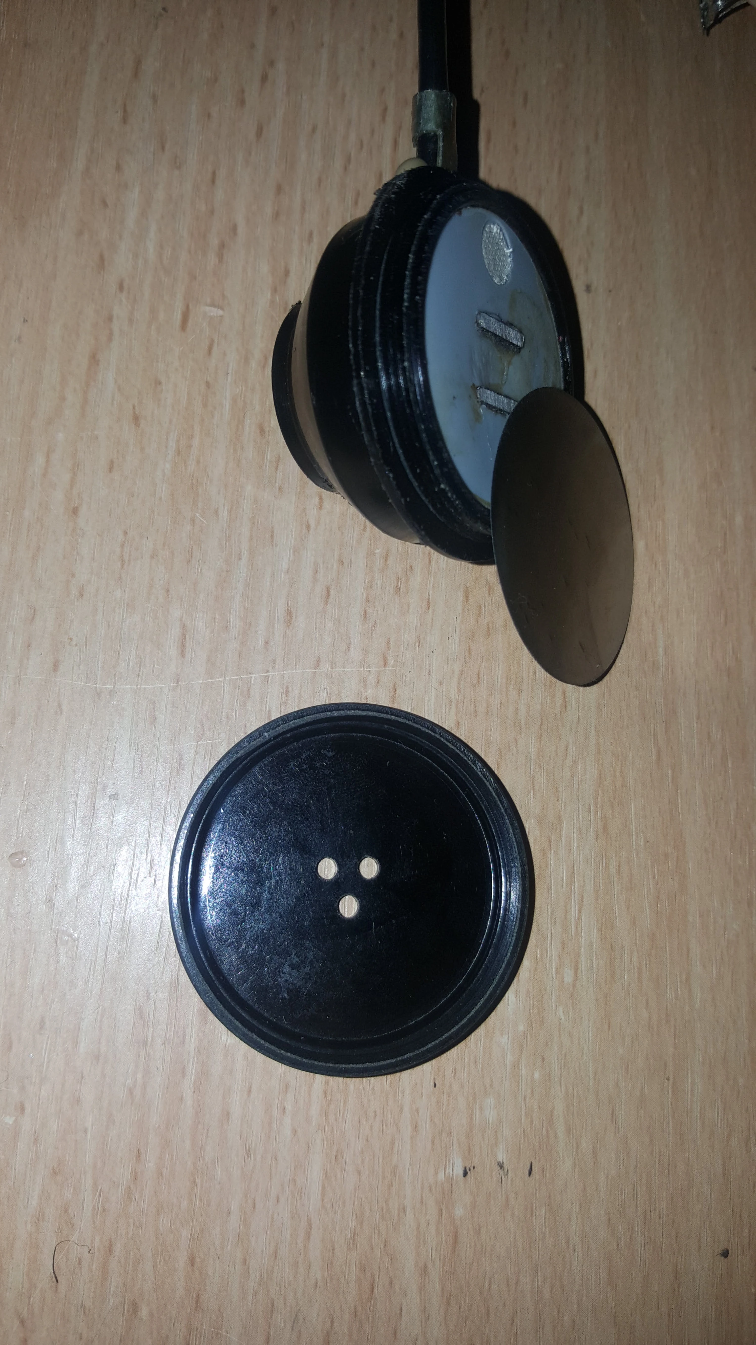

1600 ohm headset.
Larger diaphragm heads are more efficient due to the ease of movement of the diaphragm. Smartphone headsets often do not work well and they are mostly made up to 32 ohms. Cheap computer speakers, even with an amplifier, may also not work due to poor quality and inappropriate features for this purpose.
Piezo type (ZUMER) speakers work, but they aren't always the perfect choice. They are easily accessible, but often with small diameter. Larger ones can give a much better result. They also have some other problems. The most common being that zumers do not reject well the high frequencies.
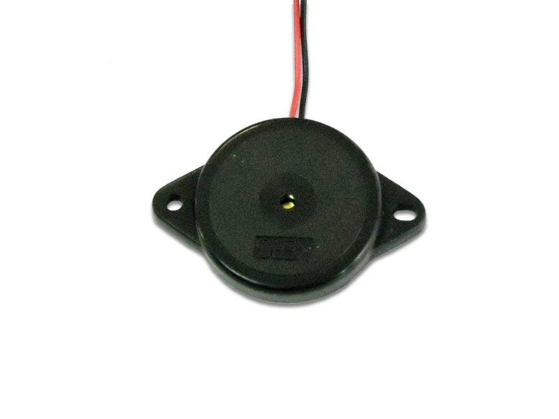

Piezoelectric zumer.
This is why they often have to be connected in parallel with a capacitor, resistor and a high impedanse choke, which can be complicate. These elements will also slightly reduce the efficiency of sound conversion. It is more difficult for them to check the working order. Good option can see here - [5] ☀This type of piezo speakers are designed to work optimally in the range of 1Khz - up to 4Khz. Sounds below and above this range will not be heard at maximum level. At high frequencies such as VHF, the headset cable may affect the tuning of the circuit so we need to use audio coaxial cable combined with chokes before input.
Sound amplifiers and preamp[]
The crystal radio output may still be too low for headphones, so a high quality sound amplifier may be required at least to pre-tune and check. The microphone input of the cassette player works well. It is also possible with a guitar amplifier. Quality sound cards too.
The advantage is that you have a sound amplifier to choose the best configuration. Often an amplifier from a single transistor and a 1.5V battery is completely sufficient for a headset. The transistor circuit may be simpler and with fewer elements than those found on the Internet. Although most transistors demodulate most frequencies, a diode may be needed for higher frequencies and VHF or special transistor is needed so the receiver can easily be used as a regenerative radio.
It is also possible to use a antenna amplifier for your antenna circuit. However, this may cause problems with setting the correct frequency. The antenna amplifier itself also works as a receiver and participates in its own resonant circuit, which also needs to be tuned. Such an amplifier is only recommended as a last option. It can also be used as a local oscillator through positive feedback. It is good to avoid connecting the inputs to the outputs of different types of amplifiers, especially if both are runing on 220V or work in different frequency bands.
The result of high frequency amplification when using only \HF amplifier, the output signal to the handset is similar to that in the case where only the sound amplifier is used. Serious amplification occurs when both types of amplifiers work together in one circuit.
Grounding[]
This is very often overlooked, but it may also depend on whether you will have a successful result. It is imperative that you have a standalone grounding conductor mainly for the low frequencies including a short, medium and long wave band, especially important for long-range reception. Most crystal radio detectors use monopole antennas, which means that their output voltage depends on the neutral ground and surrounding objects. The grounded end of the winding and the headset must be at one point.That means there should be no coil turns between them. A grounding conductor can also exhibit its own inductance if it is long enough and the frequency is high.
A bad option is to use the mains ground wire. Not only will this cause unpleasant interference to the device, but it can even be dangerous in a malfunctioning home installation. The use of a neutral-to-ground connection as an antenna should also be avoided.
If you are using the pipeline, you must make sure that the pipes are metal and continuous to the ground. In some cases, grounding can provide noise so you have to experiment in which cases it helps. In extreme cases, the lack of a grounding option is compensated by a second antenna of a simple long conductor. There are crystal detector radios with large coil diameters that do not require close grounding, but this will improve the result. Grounding a coil with a ferrite antenna is often neglected. Although this would not be a major change for a commercial radio receiver, it can be crucial for a crystal radio. For long-range use, often the magnetic component alone is not sufficient.
'Reduce thе forward voltage of the diode by heating
Heating the diode from a heat source lowers the forward voltage). The method requires very good temperature regulation. This can be a battery-powered heater or metal heated by a flame or focused light. The heating effect can also be achieved by supplying current through the diode terminals for a few seconds. With this method there is a risk of damage. Thus, the diode starts to operate at a lower voltage point, which means it can detect weaker signals. However, if the temperature is exceeded, the leakage currents will increase to a value at which the diode will have almost linear resistance and will not function properly. The beneficial effect of heating is limited and you may not reach the quality of operation of other brands of diodes or methods at normal temperature. Heat can generate static noise in many cases or cause structural changes.
Use with coaxial cable antenna[]

The use of a coaxial cable with a crystal radio detector is rare. For a midrange crystal receiver even more, since such cables have signal losses and would unnecessarily complicate the circuit. Coaxial cables have special properties and cannot be replaced by other wires.
The use of such a cable may be necessary if the distance between the receiver and the desired antenna is large, or some obstacles that may interfere with the antenna from a bare unshielded conductor have to be circumvented. Another reason may be that movement around the receiver affects its antenna. Such a phenomenon is observed at very high frequencies VHF, where the wavelengths become commensurate with the surrounding objects and body, and where coaxial cable is most often applied.
Connecting a coaxial cable to the coil of a crystal radio requires impedance matching so that the signal across the cable is not cutoff by the inductor impedance and vice versa. Therefore, almost never the two cable terminals connect exactly at the two ends of the coil or inductor frame. This will overload the circuit with capacitance. Power transfer is effective when the inner core is connected to the slightly higher potential of the coil. The outer conductor always requires it to be closer to the low potential and ideally directly conected to the grond neutral side. The number of connected windings to the cable makes a difference and this is experimentally done. The minimum is at least one turn.
☀in case direct connection is not possible then inductive coupling is an option. In an inductive coupling, the correct direction of the windings can be strongly influenced. The standard rules depending on the situation are followed for connecting an antenna to the other end of the cable. The coaxial cable alone will not work as an antenna. It is just a transmission line.
How to test crystal radio []
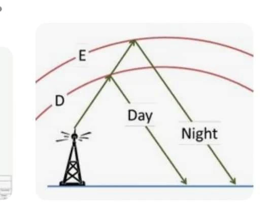
You need to keep in mind that you will need to take some free time to have a successful radio. You need to try this at different times of the day and night, since radio waves of different lengths reflect differently from the ionosphere during the day and night. Some of the powerful international midwave and SW transmitters only work a certain part of the day due to special requirements. You may not hear sound immediately after connecting the circuit, but do not give up. It is advisable to test in clear skies without fog or clouds. There may be days when you have no signal or are weak despite good conditions. It often happens during magnetic storms and bad weather in or near the transmitter. There are four layers during the day, these are (in altitude ascending order):
- the D layer
- the E layer
- the F1 layer
- the F2 layer
these are supportable during the day to varying degrees depending on:
- time of day
- time of year
- geographical location
At night, with no sun, the ionisation process stops and the lower altitude, ionically weaker-charged layers disappear. These are the D layer (which is no big practical useful even during the day) and the E layer. Even the two stronger layers, the F1 and F2 suffer from the depletion of ionisation at night and they merge to form a single, weakly ionised F layer only capable of supporting lower frequencies, typically in the range of 2MHz to 6MHz.☀The F layer is essential for the long-range propagation of shortwaves. However, none of the layers contributes significantly to VHF.

Reflected radiowaves at night.
Even if you do not hear the sound immediately, there is still a way to understand the circuitry's sound by the characteristic rumbling noise of the handset, which is different from that of the bad diode. The effect is strong only with mid-wave crystal receivers.
It is a good idea to find stronger radio broadcast in your territory or near the borders with neighboring countries. This can give a clear idea of how many coil turns you will need and what configuration (AM or FM VHF) in general. Online SDR receivers offer good research opportunities.
Possible failures in crystal radio circuits[]
'This describes possible problems in the general case and for the simplest scheme.'
'You do not hear any sound' []
- Check with a commercial radio for suitable transmitters and strong broadcast frequencies in your area. Ranges (AM, SW, FM) Medium, short and ultra short waves. Pay more attention to medium and short waves, which often use strong amplitude modulation.
Check the diode for damage and whether it is the right model at all. The diode is the most common cause of failure. The diode has the most serious energy losses for the radio, but it can't do without it. There are a large number of brands of diodes, but the common thing among those who work is that they use a glass case and have a point contact. The causes of a faulty diode may be an inappropriate minimum threshold voltage, high stray capacitance, or damaged PN junction.
- Check that the handset is working properly. It should produce noise or picks at voltages in the order of a few millivolts and even much less. If the handset is magnetic, measure the coil resistance. If it is piezoelectric you should hear a click when touch both input wires.
- 'Check the quality of the grounding especially for the reception of AM low frequencies.' It is not very important with FM VHF. In medium waves it is very important.
- The coil must not be wound on metal material and having too many turns. It will only give you grid noise. The quality of the insulation of the conductor is important if the coil is tightly wound. The thickness of the insulation must be within acceptable limits. The type of conductor material is not critical, but copper will give more efficiency.
- Check the variable capacitor. High capacity can block high frequencies or completely shorten the circuit. '
It is a common mistake to connect a random fixed capacitor in parallel to the coil, the inductor.' Not only is this wrong, but it will not give you any precise tuning. Some old variable capacitors may have short circuit in the plates.
- The antenna conductor should not touch other metal objects and is well insulated and away from the ground and floor of the room.
- If you are using an amplifier, power it with batteries, not the mains or other grid.
The sound level is too low []
- Increase the length of the antenna wire. You can use a more complicate antenna. Try moving the wire up into space and higher. The signal is stronger next to windows and outside buildings. Change the position and shape until maximum sound is obtained.
- Use a higher impedance handset. Using an impedance matching transformer will cause more losses with provided very weak signal, especially if there is also a bad matching between the transformer and the handset. In some special circuits, such a transformer is multi-winding and uses switches to find the best impedance ratio. ☀The headset should cover the ear tightly
- Replace the diode with another similar or different one. Change its position before the antenna or the grounded end of the coil. Use the classic method with pyrene and galena.
-Make experiments with (LC ratio). Try different number of turns with the same diameter of wire and form. For medium waves, use ferrite or iron powder in pakage.
- Use a simple battery powered amplifier. A single transistor is often enough. Grid-powered amplifiers always make noise and leaks killing the received signal. Choose a quiet location if you do not use an amplifier.
- 'Remove the sources of EMF interference around you. These are various chargers or power supplies, routers and mobile phones. If the sound is still low, you have reached the limit. You can't get more RF power because of the transmitter's location and its limited power and directivity. The crystal detector receiver has quite limited capabilities due to conventional materials and technology compared to modern communication digital technology.
'Performance' []
For maximum radio-to-audio conversion efficiency, your resonant circuit must have a minimum number of components that have high active resistance or signal loss due to high capacitance and excess inductance (excluding headphones or amplifier elements).
Practically a single good diode with a low forward voltage attached to a quality resonant circuit is sufficient to convert any radio wave of a given frequency range into some sound or noise, in which case it is considered irrelevant whether the output signal always contains the actual sended information .
With a strong signal available, energy could be used as a power source to receive a weaker station.
All circuits using even more than one diode and complex inductive connections are offered. Most of them are only principle or require much stronger input signals to operate properly. It is quite possible that some of them may not work at all on Bulgarian territory, or at least in your experience. More complex circuits without a power source would not make the reception much better. There are many more things that can lead to failure with more complex circuits if you don't have previous successful experience. Two or more diodes in a series create a higher forward voltage and reduce the chances of success if you don't use a high frequency amplification. The crystal detector has quite limited capabilities due to conventional materials and technology compared to modern digital communication technology.
If your crystal radio is successful, you should hear some international short and medium wave broadcasts from neighboring countries tonight (Serbia, Romania, Turkey, Greece, etc.).
During the day, with a vertical antenna and low inductance, it is possible to hear and VHF FM radio from a nearby transmitter, but with reduced audio quality. Much depends on your geographical location to neighboring and nearby transmitters.
Calculation. Is it necessary? []
If you have the right knowledge, calculation may be useful, but in most cases calculation alone does not solve all possible problems in a crystal radio. For most fans, this can even lead to more difficulties and mistakes. It is common to calculate a circuit without measuring the values of the real elements. In a such way, the coil may have a high self capacitance and make it differently tuned with the selected capacitor for the required band range. The capacitor may not even match the calculated capacitance and may goes too small or large. As described above, extremely high capacitance values should be avoided even though the calculation is close to a given frequency. The same reason why inductors and capacitors are made variable, not fixed.
In order to really make sense of the calculation, you need to be able to measure the values of the real elements, which may require the appropriate (sometimes expensive) hardware or software. Good theoretical knowledge may be required depending on the methods or software programs used.
In the real life circuit, unanticipated inductance and capacitance can occur in every single wire depending on the frequency, so the calculations according to the standard formulas will never be 100% accurate. As the frequency increases, the error also increases. ☀Many online programs do not include capacitance influence of ferrite core. However, this does not mean that the crystal radio will not work at all, but it may give an unwanted deviation when tuning the final project. However, if you still need to check and reference, there are quite a number of easy online applications available to calculate standard resonant circuits.
It would be best to use sources that describe the overall design of a crystal radio rather than simply the basic calculation of an idealized tuned circuit. To make this even easier, it is best to use the design or information from an already existing crystal radio project for the selected frequency range and subsequently upgrade it for you. Commercial radio ferrite antennas would work as crystal radio for some bands.
In general, the best successful result of making such a device is often based on long experimentation and reseach, while theory mainly provides the primary data and conditions.
Special purpose crystal receivers[]
Such crystal receivers are mainly used in laboratory experimental installations and as measuring devices in complex equipment. Such are standing wave measurements (SWR), field density (EMF), and more. Microwave detectors and video modulated converters are also being built. The output of these receivers is often not the actual transmitted information, but mainly simple voltage of the demodulated signal, which may still be encoded or not carry any actual information. One popular type is the Gunn diode detector.
More info and references[]
- ↑ http://www.rfcafe.com/references/electronics-world/truth-about-fm-electronics-world-august-1969.htm
- ↑ http://eea.government.bg/eea/en/publicat/yearbook/noise/2000/noise /prom.htm
- ↑ https://www.google.com/search?q=Foster-Seeley&client=tablet-android-samsung&prmd = ivmn & source = lnms & tbm = isch & sa = X & ved = 2ahUKEwiprNeSveziAhXN2KQKHZwxCSoQ_AUoAXoECAwQAQ & biw = 686 & bih = 1098 # imgrc = cPIZIFcKPr8BZM & imgdii = nIhow4DE
- ↑ http://astro.u-strasbg.fr/~koppen/RJove/filters.html
- ↑ https://www.aliexpress.com/item/32828133636.html?ws_ab_test=searchweb0_0,searchweb201602_0_10084_10083_10304_10546_10887_10307_321_453_10548_322_454_10618_536_10065_317_537_10068_319_10059_10103_10884_10696_10820,searchweb201603_0,ppcSwitch_0&algo_pvid=f625ba37-1077-4dee-bdb7- 89cafb00e5cc & algo_expid = f625ba37-1077-4dee-bdb7-89cafb00e5cc-1
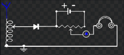
'>>' Video of how a detector radio connects through a microphone cassette amplifier ...... https: //www.youtube.com/watch? V = IN0yV-GKMQE
>> https://en.wikipedia.org/wiki/Detector_Radio
>> :: Coil 32 :: Free Android Winding Calculator application and application.
>> http://www.njqrp.club/n2cxantennas/halfer/index.html antennas
>> More schemes by other authors: http://pchelar-elektronchik.tk/statia158_21_spisak.html
>> http://leradiofil.com/detecteurs.htm
》》 Https://www.explainthatstuff.com/antennas.html
》》 Https://www.electronics-notes.com/articles/radio/modulation/fm-frequency-demodulation-slope-detector-discriminator.php Advantages and disadvantages of the slope detection method.
>> https://youtu.be/uT4JouAE2WA utilization of old semiconductors for detector.
》》 Https://youtu.be/61UqLXVJM7s Why some AM stations are not heard on different days.
>> CB AM Transmitter Information - http://bnr.bg/starazagora/page/tehnika
》》 Https://www.youtube.com/playlist?list=PLb7m6JNfYBplolryblu2WdC8OMgyn0J8a List of international AM radio transmissions.